 |
| Completed PCBA |
 |
| With connections |
To see the circuit in action, check out the video above. To read about my build process, click the jump below.
Much of this project was inspired by a tutorial I found online, linked here: http://www.instructables.com/id/Blinking-LEDs-to-the-Frequency-of-Musi/
This tutorial makes use of the MSGEQ7 IC, a spectrum analyzer that is capable of taking an audio signal input and splitting it into seven different frequency bands ready to be read by a digital host.
While recreating the linked tutorial, the biggest issue I had were with faulty MSGEQ7 ICs which would report frequency values that did not match up with the expected values. The first two chips I ordered were from a reseller in China, and both chips either had values that did not change or a frequency band that would remain at 0. I reordered a new MSGEQ7 from sparkfun, which turned out to work just fine.
During my initial testing of the original code found in the tutorial, I found that all the colors of the RGB LED Strip would often be "on" at the same time, and you could hardly tell that the strip was reacting to music. To make the changes in the frequency band more prominent, I made an adjustment in the code. In short, I took the values that were being displayed on the RGB LED Strip (e.g. spectrumValue[1]), and then proceeded to square them and then divide them by the max value of 255 (e.g. (spectrumValue[1] * spectrumValue[1]) / 255). By taking advantage of the quadratic curve, low frequency values were less visible on the RGB LED Strip, while high frequency values were more visible on the RGB LED Strip.
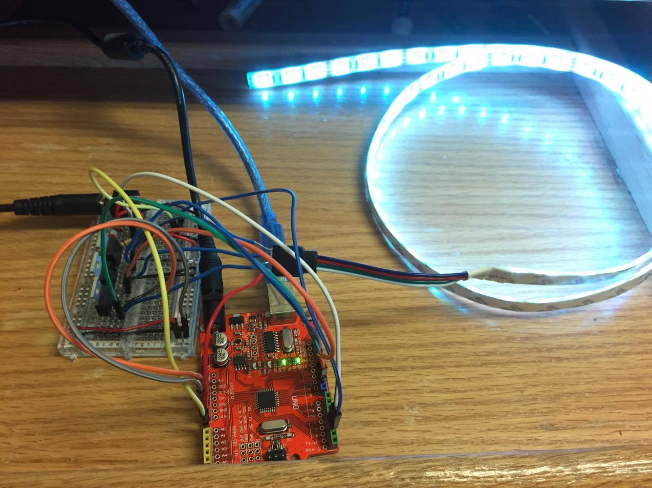 |
| Recreated project on a breadboard |
For this project, I wanted to try designing my own PCB for the first time, and I decided to use a very common software known as Eagle CAD. I also wanted to move away from the Arduino and instead use its microcontroller, the ATmega328P such that it could be placed on the PCB. Below you can view the updated schematic that I created, as well as the PCB layout as seen in Eagle CAD.
 |
| Schematic |
 |
| PCB Layout |
Before this project, I had never actually programmed a barebones ATmega328P before. To learn how to do this, I followed another tutorial found here: http://www.instructables.com/id/Atmega-Programming-with-USBtinyISP-and-Arduino/
 |
| Programming the ATmega328P with the USBtinyISP |
In the end, the PCB that I designed and had manufactured from OSH Park worked, and the project was an overall success for me. I learned how to use a ATmega328P microcontroller rather than keeping an Arduino in the final product, and I also created my first PCB. Thanks for reading about my project, and feel free to ask any questions you may have.
Can you give us you PCB layout PLS :)
ReplyDelete