 |
| Competition Day |
 |
| The car |
From November 2015 - May 2016, I was a lead designer for an autonomous line-following car. With a team of four other people, we participated in UC San Diego's Grand PrIEEE competition. The car features a TSL-1401 Linescan Camera as our sensor, a half H-bridge to drive our motor, a servo motor for turning, an Arduino as the microcontroller.
Above you can view a video of the car running a track. Click the jump below for the technical details of the car, as well as the build process that we went through over the year.
UC San Diego's Grand PrIEEE competition, based on UC Davis's Natcar, is a design competition in which undergraduate teams design and race an autonomous car which follows a 1-inch white tape on the floor. A wire carrying a 100mA rms 75 kHz sinusoidal signal is beneath the tape.
Our team consisted of members with very little experience. Consequently, we had to learn about all the subsystems that would be implemented, as well as consider all of our options.
Our team consisted of members with very little experience. Consequently, we had to learn about all the subsystems that would be implemented, as well as consider all of our options.
 |
| Block Diagram of our car |
For our microcontroller, we decided on the Arduino. This choice was mainly due to my past experience with Arduino, as I had felt confident with my knowledge to interface with it. Another choice that is popular among other competitors is the Teensy, which is a faster alternative very similar to the Arduino.
 |
| Schematic of the car |
The Camera
In our final design, we decided to use the most popular way of sensing the line: the TSL-1401 Linescan camera. The camera adds one-dimensional sight to our microcontroller, and has the ability to measure light intensity values. It has three pins that interact with the Arduino: the Clock, SI, and output pins. Looking at the datasheet for the camera, we can see that in order to start taking a "frame" (i.e. 128 pixels to form a one-dimensional image), we set the SI and Clock pins to HIGH via the Arduino. Each pixel is then taken with each cycle of the Clock pin being set to HIGH and LOW. The frame is finished when SI is set to LOW, and the process is repeated to receive a continuous image.
To detect the line, we used a gradient filter. In short, our code looked for large increases in light intensity values, which would signal the right and left edges of the white line we were detecting.
 |
| Linescan camera + 3D printed mount |
Our camera mount went through several iterations, and was designed in Autodesk Inventor. In the first iteration, our camera only had a view of about 1 feet from the front of the car. As a result, our car speed was limited by how far we could see. In the later iterations, the height of the mount was increased so that the camera could see approximately 2 feet from the front of the car, and the mount was made to be less bulky than its previous iteration. The angle was adjusted to achieve the desired viewing length.
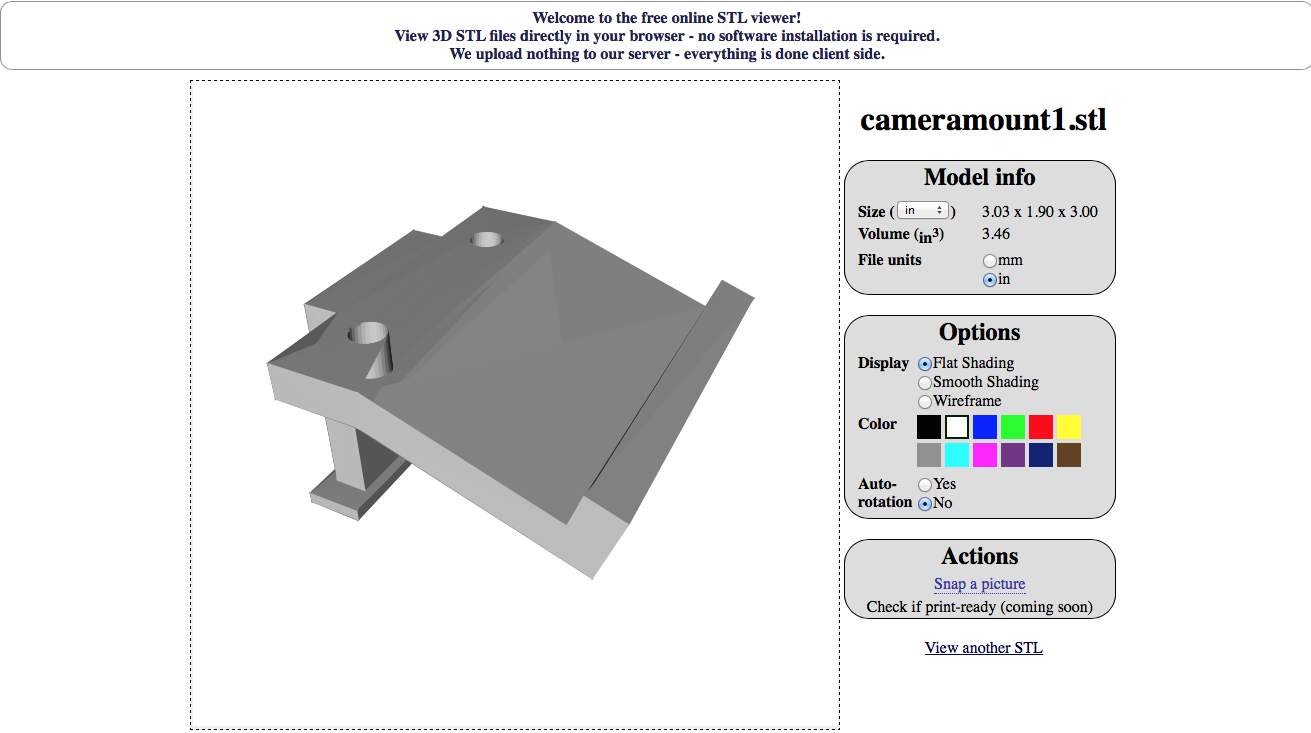 |
| First iteration of the camera mount |
 |
| Early version of our car |
The H-Bridge
One of the rules of the competition requires us to build our own motor driver circuit with the use of electrical components, as commercially available H-Bridge IC's were not allowed. This part of the car was something that our team struggled with for a while, as none of us had coursework on what a transistor was until halfway through the competition.
After doing research, we decided on a half H-bridge circuit. This would allow us to move the motor in one direction, controlling speed through PWM signals on the Arduino. PWM, or Pulse Width Modulation, works by adjusting a duty cycle. In our case, we adjust the duty cycle of a signal going into the gate of our N-Channel MOSFET, rapidly switching it on and off. Depending on the duty cycle, the motor then reads an average voltage, which ultimately controls the speed of the car.
Our circuit uses the TC427 Gate Driver. The gate driver allows the Arduino to rapidly switch the gate of the MOSFET, as the digital signals from the Arduino cannot overcome the high gate capacitance of the MOSFET. By increasing the current going into the gate, we maximize the switching speed of the gate.
 |
| Old Schematic of Half H-Bridge |
Above is an old schematic that we used. With this schematic, we encountered problems with overheating as this configuration requires both the P-channel and N-channel MOSFETs to be on at the same time. In our final design, we ended up using a totem pole configuration found in our schematic above. With this, we control the speed through the low-side N-channel MOSFET, while breaking with the P-channel MOSFET on the high-side.
The Servo Motor
To turn the wheels of the car, we use a typical servo motor found in many RC applications. The servo can easily be manipulated with the Arduino's servo library, which automates the PWM process required to change the angle of a servo. To provide power to the servo, we connected our main battery through a LM7805 Voltage Regulator. As the Arduino can only output a maximum of 200 mA through its pins, we needed to power the servo directly from the battery as servo motors can draw much more current than allowed from the Arduino. The LM7805 ensures that the servo motor receives a safe voltage of 5 V.
To turn the wheels of the car, we use a typical servo motor found in many RC applications. The servo can easily be manipulated with the Arduino's servo library, which automates the PWM process required to change the angle of a servo. To provide power to the servo, we connected our main battery through a LM7805 Voltage Regulator. As the Arduino can only output a maximum of 200 mA through its pins, we needed to power the servo directly from the battery as servo motors can draw much more current than allowed from the Arduino. The LM7805 ensures that the servo motor receives a safe voltage of 5 V.
PID Control
The three main aspects of the car: the camera, the H-Bridge, and the servo were all interfaced together using PID control on the Arduino. PID stands for proportional-integral-derivative, and in our code we were able to implement both proportional and derivative control. An excellent explanation of PID Control in terms of line following can be found here: YouTube. The proportional and derivative constants were found through trial and error.
For line following, PID Control serves the purpose of making sure that the car is always centered on the white line. To achieve this goal, we adjusted the turning angle of the servo based on where the camera was detecting the white line. So for example, if the camera saw the white line to be on the right, the servo would turn the car right. In addition, we used PID Control to adjust the speed of the motor based on the turning angle - so if the car was making a wide turn, we lowered the speed of the car.
Main issues that we ran into
We ran into many issues working on this project. While each sub-system worked individually, issues would always arise when trying to implement multiple sub-systems together.
The main issue that we ran into was electrical noise. Although we could get the servo motor and the camera to work individually, we could not get them to work together for a while. Attaching the servo motor would interfere with the readings of the camera, and give us unusable results. We later found out that rearranging the wires on our breadboard helped to remedy the noise, as the power and ground lines of the servo motor and camera were too close in proximity. When current flows through the supply lines, magnetic fields are produced which can lead to electrical noise. We also added decoupling capacitors, which also helped with any voltage spikes in our circuit being caused by noise.
Another issue that we came across was the speed of our motor. Again, this was another issue caused by the way we arranged our wires. Because our wiring was very unorganized, the two ends of our motor were going through many jumper wires before reaching the power source and the drains of the MOSFETs. This was causing the motor to run much slower than it could potentially go. We also did not realize that the diameter of the wires were important, as replacing our standard 22 AWG wires with alligator clips allowed more current to flow to the motor. In the future, we would switch to 18 or 16 AWG wire for motor applications.
Conclusion
We learned a lot from the project that we would not have learned through our coursework. Creating a project with many different subsystems that need to interact with each other, while working with a team to meet deadlines, has been an amazing learning experience. Although we did not win the competition, I'm glad we competed as just looking at the designs of other competitors can show ways to improve our design.
I will be competing again next year, as I am excited to make many improvements to our first year design of an autonomous line following car. Thanks for reading about the project, and feel free to ask any questions.
Main issues that we ran into
We ran into many issues working on this project. While each sub-system worked individually, issues would always arise when trying to implement multiple sub-systems together.
The main issue that we ran into was electrical noise. Although we could get the servo motor and the camera to work individually, we could not get them to work together for a while. Attaching the servo motor would interfere with the readings of the camera, and give us unusable results. We later found out that rearranging the wires on our breadboard helped to remedy the noise, as the power and ground lines of the servo motor and camera were too close in proximity. When current flows through the supply lines, magnetic fields are produced which can lead to electrical noise. We also added decoupling capacitors, which also helped with any voltage spikes in our circuit being caused by noise.
Another issue that we came across was the speed of our motor. Again, this was another issue caused by the way we arranged our wires. Because our wiring was very unorganized, the two ends of our motor were going through many jumper wires before reaching the power source and the drains of the MOSFETs. This was causing the motor to run much slower than it could potentially go. We also did not realize that the diameter of the wires were important, as replacing our standard 22 AWG wires with alligator clips allowed more current to flow to the motor. In the future, we would switch to 18 or 16 AWG wire for motor applications.
Conclusion
We learned a lot from the project that we would not have learned through our coursework. Creating a project with many different subsystems that need to interact with each other, while working with a team to meet deadlines, has been an amazing learning experience. Although we did not win the competition, I'm glad we competed as just looking at the designs of other competitors can show ways to improve our design.
 |
| Competition Day at UC San Diego |
I will be competing again next year, as I am excited to make many improvements to our first year design of an autonomous line following car. Thanks for reading about the project, and feel free to ask any questions.
No comments:
Post a Comment