
I ordered my first Arduino Uno on 1/24/15. It was clone Uno, part of a cheap kit from aliexpress.com. When I received it nearly two months later, I decided to build an alarm clock with the Uno, as an alarm clock would have enough functions to ease me into later, more complex projects with an Arduino. I also ordered parts that would be necessary for this project from Tayda Electronics, as well as several tools from Amazon, most notably a soldering iron.
Towards the end of March, I built two simple projects in order to familiarize myself with the Arduino IDE. The first project was a series of three blinking LED's, which would stop when a pushbutton was pushed. The second project was a laser alarm, in which a piezo buzzer would sound an alarm when a laser pointer was taken off a photoresistor.
 |
| Series of blinking LED's |
 |
| Laser Alarm |
I wanted to incorporate eight LED's into my actual alarm clock, so I began to experiment with the 74hc595 shift register to conserve the amount of pins on my Arduino. In addition, I also learned how to interface with a 16x2 LCD Display.
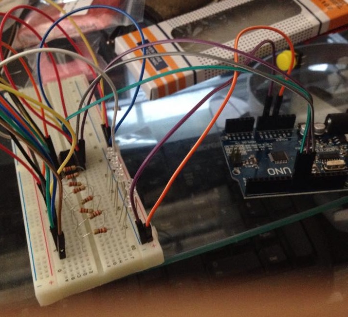 |
| 74HC595 Shift Register with 8 LED's |
 |
| 16x2 LCD Display |
 |
 |
| Completed Breadboard Prototype |
Coding took a few days to complete and was mostly done in June. I was able to use all the knowledge that I learned from all my previous experiments, combining all of them into the code for my alarm clock. The most tedious part ended up getting the text to display and constantly update to user commands.
>> Link to Code <<
Once coding was complete, the next and final step was to build an enclosure for the clock. I ended up using a simple dollar store container. The holes for the LCD display, LED's, and push buttons were made using the soldering iron as a hot knife, since I didn't have access to a drill. Originally, I decided to power the clock using 6x AA battery, but later opted to use a 9 V wall wart instead.
Once coding was complete, the next and final step was to build an enclosure for the clock. I ended up using a simple dollar store container. The holes for the LCD display, LED's, and push buttons were made using the soldering iron as a hot knife, since I didn't have access to a drill. Originally, I decided to power the clock using 6x AA battery, but later opted to use a 9 V wall wart instead.
 |

Once I wired everything to the Arduino, the project was finished. Overall, I'm really satisfied with how my first project turned out. I learned a lot that will no doubt be helpful in my future projects. If I were to revisit this alarm clock in the future with access to more tools, I would focus most of my attention on making the enclosure more polished. In addition, I would eliminate the need to use an Uno and probably wire everything directly to a ATmega328 instead.


No comments:
Post a Comment